Magnetism & Electromagnetism - 7.3.4 Transformers (HT Only) (GCSE Physics AQA)
Transformers (HT Only)
Basic Structure of a Transformer
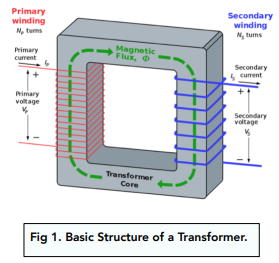
The basic transformer is made up of two coils.
These are called the primary coil and a secondary coil.
As the names suggest, they are simply just wires that have been shaped into coils (solenoids).
The primary and secondary coils of the transformer are wound around an iron core, in a similar way to the solenoids in earlier tutorials.

Using Iron
- Iron can be called an ‘induced magnet’. This means that it becomes magnetic very easily in the presence of a current. This property makes it perfect as the core of a transformer; it enables us to magnetise and use the transformer very easily.
- Iron is also very easily demagnetised. Once we stop applying the current, the iron loses most of its magnetism very quickly which allows us to switch the transformer on and off very easily.
Ratio of Potential Differences
Number of Turns Ratio
- In a transformer, we know that there is a primary and a secondary coil. The two coils do not have the same potential difference; this varies across the two.
- The pd of each coil is determined by the number of turns on each coil. The higher the number of turns on the coil, the higher the pd in that coil. We can work out a ratio of turns between the primary and secondary coils, and therefore a ratio of p.d.’s as well.
The transformer equation:

Where:
- The number of turns on the primary coil, Np
- The number of turns on the secondary coil, Ns
- The potential difference of the primary coil, Vp
- The potential difference of the secondary coil, Vs
Question: A transformer has 400 turns on its primary coil and 20 on its secondary coil. Calculate the potential difference across the primary coil if the potential difference across the secondary coil is 12 V.
1. Write out the formula.
Vp / Vs = Np / Ns
2. Write out the numbers we know.
Vs = 12V
Np = 400 Turns
Ns = 20 Turns
3. Substitute in the numbers.
Vp / Vs = Np / Ns
Vp / 12 = 400/20
Vp / 12 = 20
Vp = 20 x 12
Vp = 240V
Step Up and Step Down Transformers
In a transformer, we can change the pd between the primary and the secondary coils. We can this by adjusting each coil, by increasing or decreasing the number of turns.
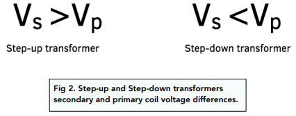
The two types of transformers are step-up and step-down transformers.
In a step up transformer, the number of turns on the secondary coil is higher than the number of turns on the primary coil.
In a step-down transformer, the number of turns on the primary coil is higher than the number of turns on the secondary coil. We can also express this like so:

Efficiency of Transformers
When we talk about electrical devices, we often talk about efficiency.
If we say that an electrical device is 100% efficient, we mean that all of the energy from the device is converted into a useful energy output.
In other words, none of the energy is wasted.
Transformers are almost 100% efficient which means the power output is slightly smaller than the power input.
Calculating Power Input and Output
For AQA exams, you should be able to use the following formula to calculate power inputs and outputs.

Where:
- Vs × Is is the power output (secondary coil) in watts, W
- Vp × Ip is the power input (primary coil) in watts, W
Question: A current of 0.2 A is supplied to the primary coil of a transformer at a potential difference of 230 V. The secondary coil has a 4.0 A current flowing through it. Calculate the potential difference across the secondary coil, assuming that the transformer is 100% efficient.
4. Write out the formula.
Vp x Ip = Vs x Is
5. Write out the numbers we know.
Ip = 0.2A
Vp = 230V
Is = 4A
Vs = ?
6. Substitute in the numbers.
Vp x Ip = Vs x Is
230 x 0.2 = Vs x 4
Vs = 46/4
Vs = 11.5 V
Effects of an Alternating Current
- We can use one alternating current to induce another current. This current will produce a second magnetic field, which will oppose the original change.
- The iron core in the primary coil of a transformer will be magnetising and demagnetising very quickly. This means that the primary coil has an alternating current. Since the two are linked, the alternating current in the primary coil can pass into the secondary coil.
Linking PD and Number of Turns
The ratio of turns on a transformer will determine the ratio of its potential differences.
- The higher the ratio of turns, the higher the ratio of the potential differences will be.
- Similarly, the lower the ratio of the turns, the lower the ratio of potential differences will be (ie the p.d.s across both coils will be very similar).
Linking Current and Power Output
We have seen the relationship linking power and current earlier in this tutorial.
- If the current input is very high, then the power output will be relatively low.
- If the current input is very low, then the power output will be very high.
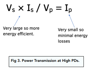
We can show this using the following equation:

When Ip is small, Vs × Is is bigger.
If Ip is big, Vs × Is then is smaller.
This also makes sense when we think about energy losses.
If our current was very high, then we would lose a lot of energy in terms of heat losses, which is not very efficient.
Power Transmission at High PDs
The output pd will affect how efficiently power is transferred from point A to point B.
We can use the number of turns in a transformer to transfer our energy more efficiently.
When power is transmitted at a very high potential difference, the power output will be at its maximum.
The current will be at a very low value, meaning that the energy transfer becomes very efficient.


Still got a question? Leave a comment
Leave a comment