


Electricity - 2.1.4 Resistors (GCSE Physics AQA)
Resistors
Types of Resistors
In the previous tutorial we introduced the concept of resistance. We learned that resistance in the circuit slows down the flow of charge (the current). For any given voltage, a higher resistance means a lower current. Resistance is measured in ohms (Ω).
There are two different types of resistors, which are both able to slow down the current in a circuit:
- Fixed resistors – fixed resistors have a constant value. Therefore, the resistance provided by a fixed resistor is constant.
- Variable resistors – variable resistors do not have a fixed value – they can change their value as the current changes.
Components in a circuit, such as lamps, will act as variable resistors. They are variable because their resistance will change depending on the current that flows through them.
Ohm’s Law
Ohm’s Law is a special relationship between current and potential difference of a component.
In simple terms Ohm’s Law is saying that if resistance is constant, then the value of the current depends on the potential difference (voltage). This makes sense if we look back at the equation V = IR.
For Ohm’s Law to hold true, there needs to be a constant temperature, because changes in temperature can lead to changes in resistance (and therefore we would no longer have a constant resistance).
Ohm’s Law gives us the characteristic straight line graph that we saw in the previous experiment.
Graph of Ohmic Conductor
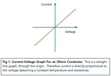
An Ohmic conductor is one that obeys Ohm’s Law. As previously mentioned, Ohm’s Law will give a straight line through origin, as shown in the current-voltage graph below.
This graph would be produced by a linear circuit. A linear circuit is one which produces a straight line graph and obeys Ohm’s Law.
Filament Lamp
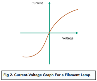
Below, we can see the current-voltage graph for a filament lamp. This type of lamp has a filament inside it. As the temperatures of the filament increases, the resistance of the filament lamp will also increase.
This graph would be produced by a non-linear circuit. A non linear circuit is one which does not produce a straight line current-voltage graph, but instead produces a curved line.

Diodes
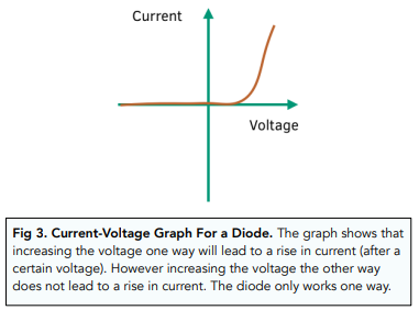
Diodes are unique, since they only allow current to flow through them in one direction. The reason behind this is to do with resistance.
Within a diode, there are 2 pathways of resistance. One has very low resistance, whilst the other has very high resistance. Current always flows through the path with the least resistance.
Below, we can see the current-voltage graph for a diode. This graph would be produced by a non-linear circuit. Remember, non linear circuit is one which produces a curved line.
Thermistors
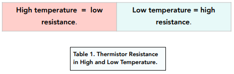
A thermistor is a special type of resistor. This resistor depends on the temperature of the surroundings. The higher the temperature, the lower the resistance.
Applications in Circuits
There are several applications of thermistors:
- Digital Thermostat – when a thermistor is placed inside a thermostat, it can sense the temperature of the surroundings. In this way, it forms part of the circuit and enables efficient temperature control of our homes. For example, if it gets too hot, the thermistor will have lower resistance, allowing more current to flow to potentially cool the room.
- Replacement Fuse – a fuse is used to break a circuit when it becomes dangerous, thus preventing an accident. Instead of using a fuse, we can use a thermistor. If too much electricity flows in a circuit, the circuit and thermistor will heat up. This increases the resistance of the thermistor, which increases the flow of current and therefore prevents the circuit from becoming dangerous.
Light Dependent Resistors
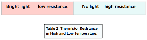
Light dependent resistors are often called LDRs. Similar to how a thermistor depends on temperature, an LDR will depend on light.
Applications in Circuits
There are several applications of LDRs:
- Burglar Detectors – LDRs can be used in burglar detectors. When light falls on the sensor, the resistance will decrease. This allows a signal or security alert to be triggered. In this way, LDRs can be used as part of a security system.
- Street Lights – LDRs can be used in automatic street lights. They work by using the light in the surroundings, and therefore can switch the streetlights on and off appropriately.
Measuring Current and PD in a Circuit
Current in a Circuit
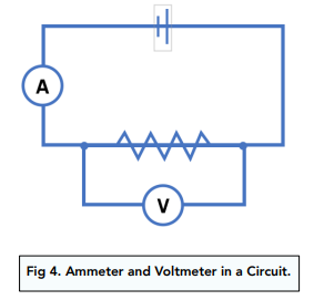
- Current is measured with an ammeter. As we learnt before, in order to measure current in a circuit, we have to use an ammeter. This will give us a value for the current in amps.
- Ammeters must be in series. The ammeter must be connected in series. In a series circuit, the current through every component will be the same. By connecting the ammeter in series, we can gain accurate values for the current through any of the components in the circuit.
Potential Difference in a Circuit
Voltage is measured with a voltmeter. As we learnt before, in order to measure pd in a circuit, we have to use a voltmeter. This will give us a value for the potential difference in volts.
Voltmeters must be in parallel. The voltmeter must be connected in parallel. In a parallel circuit, the potential difference through every component will be the same. By connecting the voltmeter in parallel, we can gain an accurate value for the potential difference across which the voltmeter is connected.
Investigating I-V Characteristics
We can investigate the I-V characteristics of three different circuit elements: a filament lamp, a diode and a resistor at constant temperature. First we will look at the experimental-setup, before analysing the graphs we get for each element.
The graphs are the same ones we studied above.
Method for Filament Lamp
- Set up a circuit. Set up a circuit with a cell, an ammeter, variable resistor and a filament lamp in series. Attach a voltmeter in parallel across the filament lamp. In the experiment, we need to ensure that the temperature stays constant.
- Alter the current. Change the current in the circuit by moving the variable resistor. This will change the resistance in the circuit, therefore altering the current flow through the filament lamp.
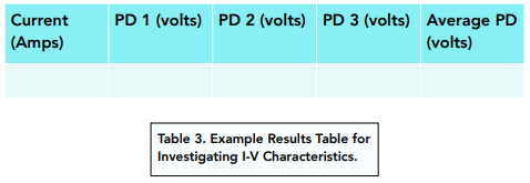
- Record values for current and voltage for a given resistance. For a given resistance, record a value for the current (from the ammeter) and the potential difference (from the voltmeter), in the results table below.
- Repeat step 3 two more times. Repeat step 3 twice. You should keep the same resistance, so the current stays the same, but you might get slightly different values for potential difference. After, find an average pd for each value of current. This step improves reliability.
For a filament lamp, the graph should look like this one below. The graph has negative values for current and PF because we switched over the wires to reverse the direction of current flow.
You can repeat the experiment with a diode and a resistor. These will give you different graphs.
A resistor is an electrical component that is used to control the flow of electric current in a circuit.
A resistor works by converting electrical energy into heat energy, which reduces the flow of current in a circuit.
The unit of resistance is the ohm (Ω).
The relationship between resistance, current, and voltage in a circuit is described by Ohm’s Law, which states that the current in a circuit is directly proportional to the voltage and inversely proportional to the resistance.
Resistors are represented in circuit diagrams by a zigzag line, with the value of the resistance written next to it.
The factors that affect the resistance of a resistor include the material it is made of, its length, its cross-sectional area, and its temperature.
A variable resistor, also known as a rheostat, is an electrical component whose resistance can be changed manually, whereas a fixed resistor has a set resistance value that cannot be changed.
Some practical applications of resistors include regulating the voltage in electrical circuits, controlling the speed of electric motors, and protecting electronic devices from excessive current flow.
Resistors are rated according to their resistance value, tolerance (i.e., the range of values that the actual resistance can be within), and power rating (i.e., the maximum amount of power that can be dissipated without damaging the resistor).
Still got a question? Leave a comment
Leave a comment