


Electricity - 2.2.3 Current, Resistance and Potential Difference (GCSE Physics AQA)
Current, Resistance and Potential Difference
Potential Difference
Cells and Batteries
As we said above, cells or batteries are required to move charge around the circuit. They are like ‘electron pumps’. In a circuit you can have cells / batteries and components:
- Cells or batteries – The cells or batteries transfer energy to the charge as it passes in the circuit. The energy given to the charges as they pass is measured in volts (V).
- Components – in contrast, components take energy away from charge as it passes. For example, a buzzer uses energy to produce sound.
Voltage
- Voltage is the energy transferred per coulomb of charge. We can define voltage (potential difference) as the energy transferred per coulomb of charge that passes. It is measured between two points in a circuit.
- Voltage means different things for cells/batteries and components. For cells or batteries, the voltage tells us the amount of energy given to the charges in the circuit. For components, the voltage tells us the amount of energy taken away from the charges in the circuit.
Voltmeters and Ammeters
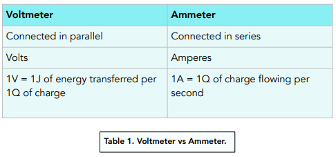
Voltmeter
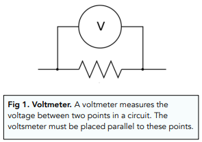
Voltages are measured using voltmeters.
Remember, a voltage for a component or cell is the energy transferred per coulomb. The voltmeter therefore measures the energy before and after the component to see the difference. So the voltmeter measures voltage (potential difference) across two points.
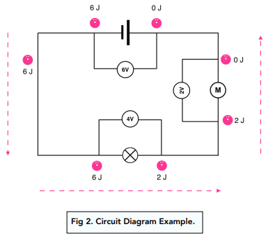
This diagram shows 1 coulomb of charge moving around a circuit.
- At the cell, the charge gets given 6J of energy, so the cell has a voltage of 6V (6J per coulomb of charge that passes). The voltmeter measures the difference in energy from before (0J) to after (6J) to work out the voltage.
- At the lamp, the charge loses 4J of energy, so the lamp has a voltage of 4V. The voltmeter measures thedifference in energy from before (6J) to after (2J),
- At the motor, the charge loses 2J of energy, so the lamp has a voltage of 2V. The voltmeter measures the difference in energy from before (2J) to after (0J).
The voltage of the cell is always split amongst the components – none is left over.
Ammeter
The current flowing through a component is measured by an ammeter.
Whereas the voltmeter had to be in parallel, the ammeter must be connected in series. In series circuits, current is the same everywhere in the circuit (as we will see later on), so it doesn’t matter where the ammeter is placed in the circuit.
Current is measured in amperes (A).

Resistance
Resistance in the circuit slows down the flow of charge (the current). For any given voltage, a higher resistance means a lower current.
You can have resistors as actual components in circuits, but wires, lamps, motors and other components all have some elements of resistance.
Resistance is measured in ohms (Ω).
We can measure resistance of a single component by looking at the current that flows through it (A) and the voltage applied across its ends (V). The higher the resistance, the lower the current for any given voltage.
Calculating Current, Voltage and Resistance
The current flowing through a component depends on two things: the resistance of the component and the potential difference across the component. If we are given two of the current, voltage and resistance, we can calculate the third.
Where:
- potential difference, V, in volts, V
- current, I, in amperes, A (amp is acceptable for ampere)
- resistance, R, in ohms, Ω
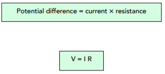
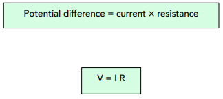
Calculating Potential Difference
We can calculate potential difference using the following equation.
Where:
• potential difference, V, in volts, V
• current, I, in amperes, A (amp is acceptable for ampere)
• resistance, R, in ohms, Ω
Question: A series circuit has a lamp, an ammeter, a 4Ω resistor and an 8V cell. Assuming the lamp and ammeter are resistance-free, what is the current reading on the ammeter?
1. Write out the equation.
In this instance, we need to rearrange the equation to find the current.
V = IR
I = V / R
2. Substitute in the numbers.
I = 8 / 4
I = 2 amps
Investigating the Resistance of Circuits
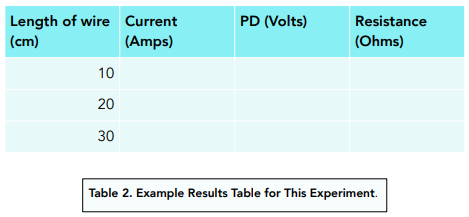
We can investigate the factors affecting resistance of circuits using the following method.
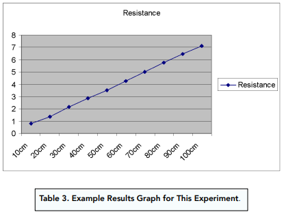
In this method, we will be varying the length of wire in this circuit.
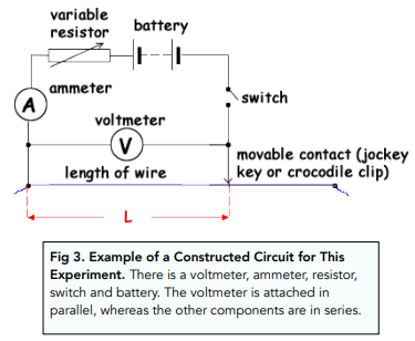
Method
- Construct a circuit. Using an ammeter, voltmeter, switch and a variable resistor, set up the circuit shown below. Add a length of wire to the circuit, which should be movable as shown below.
Current in electricity refers to the flow of charged particles, usually electrons, through a conductor such as a wire. It is measured in units of Amperes (A) and is often represented by the symbol “I”.
Resistance in electricity refers to the opposition to the flow of current in a conductor. It is measured in units of Ohms (Ω) and is often represented by the symbol “R”. Factors that affect resistance include the material of the conductor, its temperature, and its cross-sectional area.
Potential difference, also known as voltage, in electricity refers to the electrical energy per unit charge that is available to drive the flow of current through a circuit. It is measured in units of Volts (V) and is often represented by the symbol “V”.
The relationship between current, resistance, and potential difference in an electrical circuit can be described by Ohm’s Law, which states that the current in a circuit is directly proportional to the potential difference (voltage) and inversely proportional to the resistance. This can be expressed mathematically as I = V / R.
The length of a wire can affect its resistance because the longer the wire, the greater the number of atoms that the current has to flow through. This can cause increased collisions between the charged particles and the atoms of the conductor, leading to an increase in resistance.
The cross-sectional area of a wire can affect its resistance because a larger cross-sectional area provides a larger path for the charged particles to flow through, reducing the number of collisions between the particles and the atoms of the conductor. This can lead to a decrease in resistance.
The temperature of a wire can affect its resistance because an increase in temperature causes the atoms of the conductor to vibrate more, leading to an increase in collisions between the charged particles and the atoms of the conductor. This can result in an increase in resistance.
Direct current (DC) is a type of current in which the charged particles flow in a single, constant direction. Alternating current (AC) is a type of current in which the direction of flow of the charged particles changes periodically. AC is used for electrical power transmission because it can be transmitted over longer distances with less energy loss compared to DC.
The unit of power in electricity is the Watt (W), which is a measure of the rate of energy transfer. The power in a circuit can be calculated as the product of the current and the potential difference (voltage).
Still got a question? Leave a comment
Leave a comment