


Potential Dividers
A commonly employed circuit component is the potential divider, which operates on the principle that the voltage decrease across a section of a wire with constant current and uniform cross-section is proportionate to its length. The volume control of audio systems, as well as sensory circuits using light-dependent resistors and thermistors, utilize potential dividers.
Potential Divider
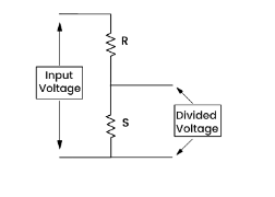
A potential divider is comprised of two resistors, R1 and R2, connected in series such that the current, I, passing through them is equal. The voltage across R1 is V1 while that across R2 is V2. The voltage drop across the resistors can be expressed mathematically using Ohm’s law.
V1 = IR1 and V2 = IR2
Dividing V1 by V2

With the aid of the aforementioned equation, it can be deduced that the total voltage (V) is distributed between the two resistors in accordance with the ratio of their resistances. By selecting suitable resistor values, the voltage across the resistors can be adjusted.
Circuit Utilizing Potential Divider
- According to Kirchhoff’s second law, when two resistors are connected in series, the potential difference from the power source is distributed between them
- Potential dividers are circuits that produce an output voltage that is a fraction of the input voltage
- The primary objectives of potential dividers are:
- To generate an adjustable potential difference
- To enable the selection of a specific potential difference
- To divide the potential difference from a power source between two or more components
- Potential dividers are extensively utilized in volume controls and sensory circuits that incorporate LDRs and thermistors
- Potential divider circuits rely on the ratio of voltages across components. This ratio is equivalent to the ratio of resistances of the resistors shown in the diagram below, resulting in the following equation:
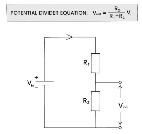
- Both ends of the series resistors are connected to the input voltage Vin
- Vout is measured between the center and the bottom of R2
- The potential difference V across a resistor depends on its resistance R:
- The resistor with a higher resistance will have a larger potential difference than the other one, according to V = IR
- Increasing the resistance of one resistor will cause it to receive a larger share of the potential difference, while the other resistor will receive a smaller share
The potential difference across a component in a potential divider circuit is proportional to its resistance, according to V = IR
Variable Resistance Components
- Potential dividers utilize variable and sensory resistors to modify the output voltage
- This alteration can lead to the activation or deactivation of an external component, such as an automatic shutdown of a heater when the ambient temperature reaches room temperature
- Light Dependent Resistors (LDRs) and thermistors are examples of sensory resistors that are frequently utilized
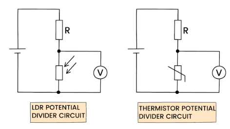
- The output voltage Vout is being measured by the voltmeter in both circuits
- It is important to remember that the resistance of an LDR is influenced by the level of light
- When the light intensity increases, the resistance decreases, and vice versa
- LDR circuits are commonly used in streetlights and security lights
- The resistance of a thermistor varies in response to temperature
- When the temperature rises, the resistance decreases, and vice versa
- Thermistor circuits are employed in fire alarms, ovens, and digital thermometers.
- According to Ohm’s law V = IR, the potential difference Vout across a resistor in a potential divider circuit is directly proportional to its resistance
- When the resistance of an LDR or thermistor decreases, the potential difference across it decreases as well
- When the resistance of an LDR or thermistor increases, the potential difference across it increases as well
- Since the sum of potential differences across all components in the circuit must equal Vin, if the potential difference across a sensory resistor decreases, the potential difference across the other resistor in the circuit must increase and vice versa
The Potentiometer
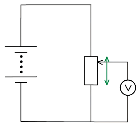
- A potentiometer is a variable resistor that is utilized as a potential divider to provide an output voltage that can be adjusted continuously
- It can be employed to compare potential differences between various locations in a circuit
- A circuit symbol that includes an arrow next to the resistor denotes a potentiometer
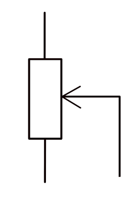
- The most basic form of a potentiometer is a single component with a sliding contact situated at the midpoint of a wire coil
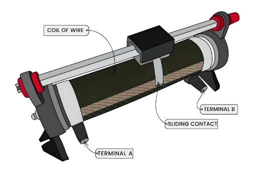
- Its circuit symbol features a resistor with a sliding contact
- The sliding contact separates the potentiometer into two distinct sections (an upper and lower section), each with a unique resistance
- If the slider in the aforementioned diagram is pushed upward, the resistance of the lower section will increase, and consequently, the potential difference across it will increase as well
- As a result, the variable resistor can attain a maximum or minimum output voltage value
- If the resistance equals 3 Ω:
- The maximum voltage is achieved when the resistance is 3 Ω
- The minimum voltage is achieved when the resistance is 0 Ω

The Galvanometer
- A galvanometer is an ammeter that is highly sensitive and is utilized for detecting electric current
- It is employed in a potentiometer to measure the electromotive force (e.m.f.) between two points in a circuit
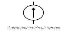
- The circuit symbol of a galvanometer is represented by an arrow in a circle:
- A galvanometer is constructed from a coil of wire that is wound around an iron core, which rotates inside a magnetic field:
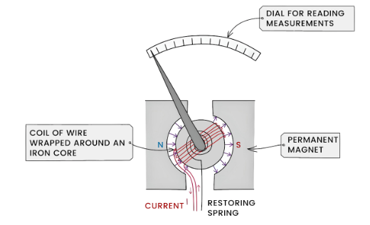
- The arrow represents a needle that moves in response to the amount of current flowing through it
- If the needle points directly upwards, there is no current flowing through it
- This is known as null deflection
- According to Ohm’s law, the current flowing through a conductor (wire) is directly proportional to the potential difference across it, implying that no potential difference results in no current flowing through the galvanometer
- When the potential on both sides of a galvanometer are equal, the galvanometer has zero potential difference (p.d.)
- The position on the wire where the galvanometer is connected (which varies with the sliding contact) gives a p.d. equal to the electromotive force (EMF) of the cell connected to the galvanometer
- To ensure that the potential of the cell opposes the potential on the wire, the positive terminal of the power supply should face the positive terminal of the cell:
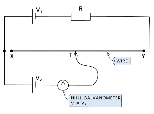
- By moving the sliding contact along the potentiometer wire, you can add or remove resistance from the external circuit, changing the potential drop across X and Y
- The sliding point is adjusted until the galvanometer reads zero, which means the potential difference equals E2
- Since the two EMFs are opposing each other in direction, there is no current flowing through the circuit
A potential divider is a circuit that divides a voltage into two or more smaller voltages. It is commonly used in electronics to adjust the level of a voltage signal or to measure voltage accurately.
A potential divider works by using two resistors in series. The input voltage is applied across the two resistors, and the output voltage is taken across one of the resistors. By selecting the values of the resistors appropriately, the output voltage can be adjusted to a desired level.
The output voltage of a potential divider can be calculated using the formula Vout = Vin * (R2 / (R1 + R2)), where Vin is the input voltage, R1 is the resistance of the first resistor, and R2 is the resistance of the second resistor.
Potential dividers have many practical applications in electronics, such as volume controls in audio equipment, brightness controls in displays, and voltage regulators in power supplies.
Potential dividers can be used as voltage dividers to measure an unknown voltage. By selecting one resistor to be a variable resistor, the output voltage can be adjusted until it matches a known voltage. The ratio of the resistances can then be used to calculate the unknown voltage.
The resistance of a variable resistor can be calculated using the formula R2 = (Vout * R1) / (Vin – Vout), where Vin is the input voltage, Vout is the desired output voltage, and R1 is the resistance of the other resistor in the potential divider.
Some common mistakes to avoid when working with potential dividers include using resistors with values that are too low or too high, not taking into account the tolerance of the resistors, and not considering the effects of temperature on the resistances.
Some common problems with potential divider circuits include incorrect output voltage, fluctuating output voltage, and voltage drops across the resistors. To troubleshoot these problems, check the values of the resistors, check for loose connections, and use a multimeter to measure the voltages at different points in the circuit.
A voltage regulator can be created by using a potential divider to feed back a portion of the output voltage to the input. This can help to stabilize the output voltage and compensate for changes in the input voltage or load. By selecting appropriate values for the resistors, a voltage regulator circuit can be designed to provide a constant output voltage.
Still got a question? Leave a comment
Leave a comment