


Combinations of Resistors
Series and Parallel Configurations of Resistors:
Resistors Connected in Series
- When two or more components are linked in a series connection:
The total resistance of the components equals the summation of their individual resistances
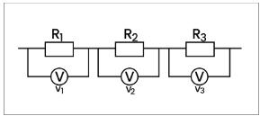
For determining the total resistance of resistors connected in series, one can use the following method:
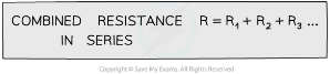
Resistors in Parallel
- When two or more components are linked in a parallel connection:
- The sum of the reciprocals of the individual resistances is equal to the reciprocal of the combined resistance
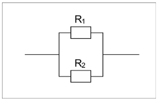
For calculating the total resistance of resistors in parallel:
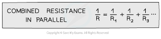
- This implies that the combined resistance decreases as more resistors are added, and is thus lower than the resistance of the individual components
- For instance, if two resistors of equal resistance are connected in parallel, the combined resistance will be half of their individual resistance.
Series & Parallel Circuits
Current
- In a series circuit, the current flowing through each component is identical.
- In a parallel circuit, the current is divided among the different branches or junctions. The total current flowing into a junction is equal to the total current flowing out of it.
- The magnitude of current in each branch depends on the total resistance of the components present in that particular branch.
Potential Difference
- In a series circuit, the voltage of the power supply is distributed unevenly among the components based on their respective resistances
- In a parallel circuit, the voltage of all the components present in a given branch is equivalent to the voltage of the power supply
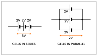
- Cells can be connected either in series or parallel
- The total voltage of the combined cells can be determined using the same method as for individual cells.
- If the cells are connected in series, the total voltage across the chain of cells is equal to the sum of the potential differences across each cell
- If the cells are linked in parallel, the total voltage across the configuration is equal to that of a single cell
- Below is a summary of the current, voltage, and resistance characteristics in a series and parallel circuit:
Table illustrating Voltage, Current, and Resistance in Series and Parallel Circuits
Conservation of Charge & Energy
Charge Conservation
- Charge is conserved in a circuit, meaning it is neither lost nor consumed
- Therefore, in a parallel circuit:
The sum of the currents flowing into a junction is always equal to the sum of the currents flowing out of that junction.
- This principle is also called Kirchhoff’s First Law
- In a circuit:
- A junction refers to the point where at least three paths in a circuit intersect
- A branch is a path linking two junctions
- If a circuit divides into two branches, the current before the split should be equal to the current after the split
- In the diagram below, the current in the circuit before it branches is represented as I, while I1, I2, and I3 indicate the current in each of the three branches. Thus, I = I1 + I2+ I3:
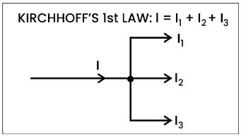
- This principle indicates that charge is conserved on both sides of the junction
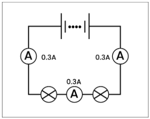
- In a series circuit, the current is constant across all components, and it remains the same at each point in the circuit
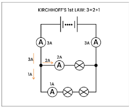
- In a parallel circuit, the current divides at the junctions, causing each branch to have a unique current value
- Kirchhoff’s First Law applies at each junction
Conservation of Energy
- The principle of conservation of energy indicates that energy cannot be destroyed or created within a circuit
- As a result of this, for voltage in any circuit:
The total electromotive force (e.m.f.) in a closed circuit is equivalent to the sum of the potential differences across each component
- This concept is also known as Kirchhoff’s Second Law
- Each closed circuit can be considered as a series circuit
- The circuit below demonstrates Kirchhoff’s Second Law, where the sum of the voltages in the closed series circuit is equal to the total e.m.f.:
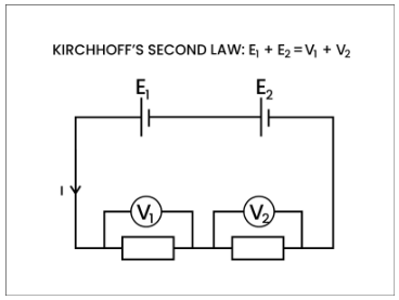
- In a series circuit, the voltage is distributed among all components based on their resistance, and the total voltage is equal to the total e.m.f. of the power supply.
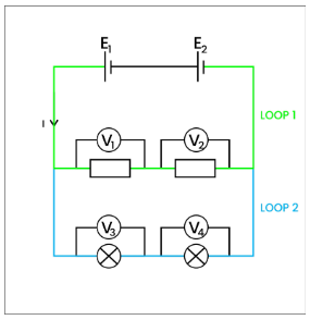
- In a parallel circuit, the voltage across each closed loop is the same, and the sum of the voltages in each closed circuit loop is equivalent to the total e.m.f. of the power supply:
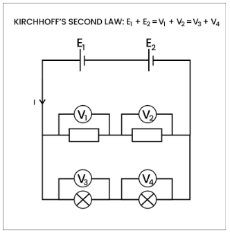
Each closed-circuit loop behaves as an independent series circuit and is separated at a junction. A parallel circuit is comprised of two or more of these closed loops
- Parallel circuits are highly advantageous for household wiring systems due to the following reasons:
- All the lights and appliances are supplied with the same voltage from a single power source
- In case a light or an appliance stops working, the voltage and current can still flow through the rest of the circuit without any interruption
Resistors in parallel
The situation becomes more complex when dealing with resistors in parallel, and it’s helpful to consider it in simple terms. Unlike in a series circuit, in a parallel circuit, the current divides at junctions. Each unit of charge receives a specific amount of energy from the cell, and it utilizes that energy only as it passes through a resistance. In the diagram below, each orange dot represents 1C of charge carrying 1J of electric potential. At the junction, the charges either continue straight or take the right branch. Since the resistance of each branch is the same, the same amount of current flows through each. As each charge passes through the resistance, it does 1J of work, resulting in a potential difference of 1V across each branch.
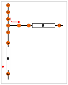
We can observe that while the current on each branch is lower than the current before the junction, the energy carried by each coulomb of charge remains constant before and after the junction. Furthermore, we can also utilize Kirchhoff’s laws to analyze this configuration:
- The current flowing through each branch may be less than the current before the junction, but their sum remains equal to the current before the junction. This observation satisfies the first law of Kirchhoff’s circuit laws.
By considering each branch as a distinct loop, we can observe that the potential difference on each branch is equivalent to the electric potential energy held by each coulomb of charge (i.e., the emf) before the junction. This aligns with the second law.
Combinations of Resistors in Series and Parallel
An electrical resistor is a passive component with two terminals that provides electrical resistance in a circuit. Resistors restrict the flow of current and decrease voltage levels within circuits. Circuits usually have multiple resistors to regulate the flow of charges. The two basic combinations of resistors are series and parallel, and this article will focus on discussing these combinations.
A circuit is comprised of various components including conductors, power sources, loads, resistors, and switches. These components work together to create a path for electrical current to flow. Conductors, typically made of copper wire without insulation, serve to transmit electrical current throughout the circuit. Switches allow for the circuit to be turned on or off. Resistors, which are passive elements that only consume power, regulate the flow of electric current in the circuit. Loads consume electrical energy and convert it into other forms of energy, such as light or heat. Examples of loads include light bulbs and fans. In this article, we will focus on resistors in series and parallel combinations.
Need of a Combination Circuit
In electric circuits, the components can be connected in either series or parallel to form various resistive networks. Resistors within the same circuit can also be connected in series and parallel across different loops, creating mixed resistor circuits that are more complex. However, it is essential to determine the total resistance of the circuit, as resistors are typically part of a larger circuit with multiple resistors connected in various combinations. Thus, it is crucial to understand how to calculate the total resistance of resistors in series and parallel circuits. In the following section, we will explore how to find the total resistance for resistors in series and parallel combinations.
Resistors can be connected in series, where they are connected end-to-end, or in parallel, where they are connected side-by-side.
The total resistance of resistors connected in series is equal to the sum of the individual resistances.
The total resistance of resistors connected in parallel can be calculated using the formula 1/Rtotal = 1/R1 + 1/R2 + 1/R3 + …, where R1, R2, R3, etc. are the individual resistances.
Connecting resistors in series can increase the overall resistance in a circuit.
Connecting resistors in parallel can decrease the overall resistance in a circuit.
The voltage drop across each resistor in a series circuit is proportional to its resistance. The voltage drop can be calculated using the formula V = IR, where V is the voltage drop, I is the current, and R is the resistance.
The current through each resistor in a parallel circuit is proportional to its conductance (the inverse of resistance). The current can be calculated using the formula I = V/R, where I is the current, V is the voltage, and R is the resistance.
A voltage divider circuit is a circuit that uses two resistors connected in series to divide a voltage into two smaller voltages.
The output voltage of a voltage divider circuit can be calculated using the formula Vout = Vin x (R2 / (R1 + R2)), where Vin is the input voltage, R1 and R2 are the two resistors in the circuit, and Vout is the output voltage.
A potentiometer is a variable resistor that can be used to vary the resistance in a circuit.
The total resistance of a potentiometer can be calculated using the formula Rtotal = R1 + R2, where R1 is the resistance of one end of the potentiometer, R2 is the resistance of the other end, and the wiper (the movable contact) is ignored.
Still got a question? Leave a comment
Leave a comment